Restorations
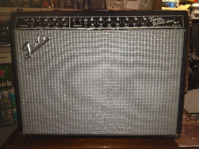
1965 Fender Twin Reverb
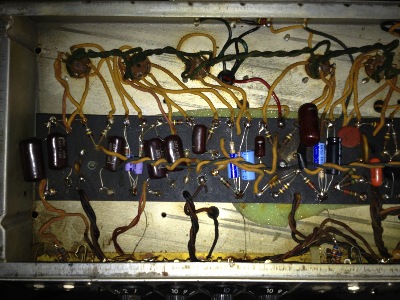
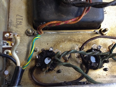
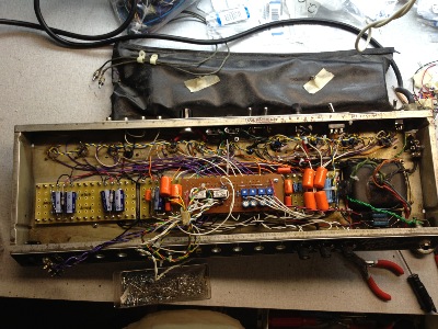
It was a deathtrap when we received it ... no insulation under the circuit card, just rusty, water damaged, foam rubber.
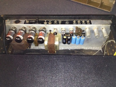
More deathtrap, ... no cover on the external power supply capacitors. Anyone could reach their hand around and get electrocuted. The bit of yellow on the right was from a sticker from a local music shop repair tech...who should be in jail for letting this leave the shop in this condition.
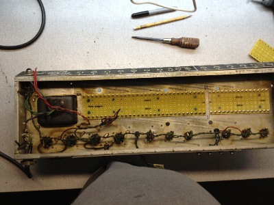
A blank canvas.
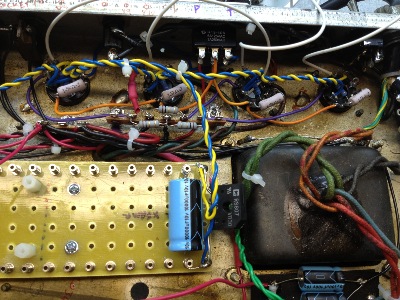
Low noise starts with a "star" ground bus.
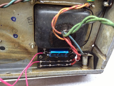
New rectifier ...
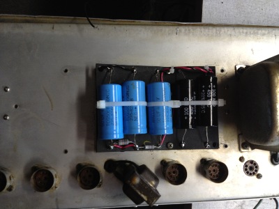
New power supply filter capacitors, and yes we got a new cover ...
New turret boards on stand offs, filament wiring, filament rectifier and filter capacitor on the right...
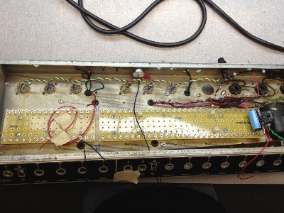
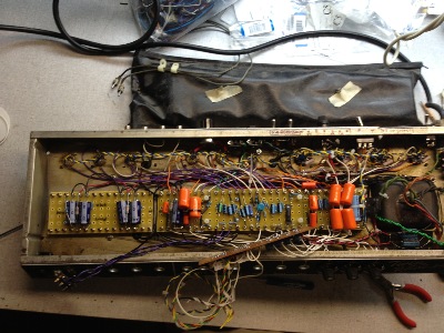
New octal sockets for power amplifier, cathode current measuring resistors, pentode/triode half power switch.
Build up the power amplifier with bias circuitry.
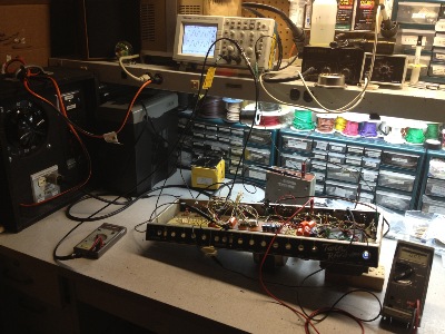
Testing the power amplifier...
- DC meter measuring bias currents and voltages with no signal
- Audio frequency generator
- 200W Power Resistor load box
- Fused and Variable mains safety circuit
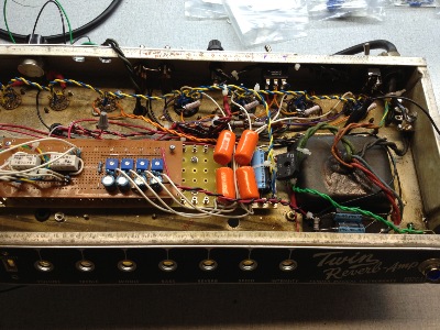
Building up the preamplifier, testing the spring reverb.
Installing the bias / channel switching board
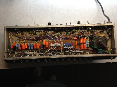
Done with wiring and testing the audio and channel switching circuits.
Now turn attention to the cabinet ... needs some clean up!
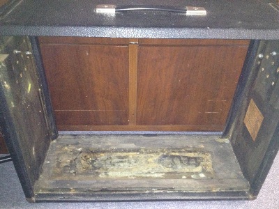
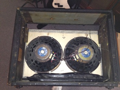
Installing permanent sound board and grille.
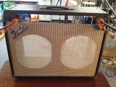
Installed the re-coned Fender speakers and spring reverb tank.
Install the chassis and new back panels.
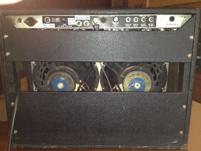
Done, time to jam!!!